The Anatomy Of A Running Program
From day one using a modern home computer, users are exposed to the concept of a program. Support for separate programs is, after all, the main value-add of multitasking operating systems. But—if we take a peek under the hood—a program is a high-level term which refers to many lower level mechanisms and concepts, and it isn’t obvious from the outset how they’re all arranged.
To unpack debuggers—programs which analyze the execution of other programs—it’s important that we first unpack the concept of a program, so that we’re familiar with the details of programs that a debugger must contend with.
Programs are the virtualized equivalent of cartridges for an old video game console, like the Nintendo Entertainment System. The NES didn’t have a multitasking operating system, and it only executed a single program while it was turned on—whatever one was stored on the cartridge that the player installed.
In this context, the program executing on the system had full availability to all of the system’s resources. There was no code running of which the program couldn’t be aware.
Programs, in the context of a multitasking operating system, are a bundle of mechanisms used to approximately provide the same thing virtually as the NES provided to the program stored on the cartridge physically. Of course, multitasking operating systems also provide ways for these programs to communicate and interact (that is indeed the point), but at some level they must still exist independently, as different physical cartridges do.
Because programs, unlike cartridges, can be executing on the same chip at the same time, and thus contend for the same resources, there are many additional software concepts that operating systems use to virtualize independent program execution:
-
A virtual address space — A range of virtual addresses, for which the platform provides a mapping to physical addresses. Programs are built to interact with virtual addresses, which are entirely independent from addresses in other virtual address spaces. Virtual address spaces can be much larger than, for example, physical RAM limitations.
-
A thread of execution — A bundle of state which is used to initialize the CPU to coherently execute a sequence of instructions. Threads of execution are scheduled by the platform, such that many threads can execute on a small, fixed number of cores.
-
An executable image — A sequence of bytes encoding data in a platform-defined format, to encode executable machine instructions, as well as relevant headers and metadata. An independent code package’s non-live representation—a blueprint for execution.
-
A loader — The part of an operating system responsible for parsing executable images—blueprints for execution—and instantiating them, so that the code encoded in the images may be actually executed.
-
A module — The loaded equivalent of an executable image. One process can load several modules, although a process is always initialized by the loading of one specific module (the initial executable image). Modules can be both dynamically loaded and unloaded.
-
A process — An instance of a live, running program. Instantiated by the platform’s loader using the initial executable image to determine how it’s initialized, and what code is initially loaded. The granularity at which operating systems assign virtual address spaces. The container of several modules, and threads of execution.
Let’s unpack all of this.
A range of virtual addresses, for which the platform provides a mapping to physical addresses. Programs are built to interact with virtual addresses, which are entirely independent from addresses in other virtual address spaces. Virtual address spaces can be much larger than, for example, physical RAM limitations.
Whether it’s through the easy or hard way, all programmers learn about pointers. When I first learned about pointers, I understood them as being used to encode integers, with the integers being addresses, which address bytes within memory, in linear order. Address 0 comes before 1, which comes before 2, and so on.
In other words, I was under the impression that physical memory, and its relationship to addresses, was structured like this:
This is a fine mental model to begin with. But it isn’t accurate.
When many independent programs execute on a single machine, it isn’t difficult to imagine one of them getting an address wrong. In fact, sometimes, it feels like “getting addresses wrong” is the only thing anybody talks about these days. If all of these programs shared a single memory space, this could easily lead to one program stomping over data that another program is using. It could also lead to, for example, a malicious program—let’s call it ryans_game.exe—reading information from chrome.exe, browsing a page from chase.com with all of your sensitive information on it. This is purely hypothetical!
Virtual address spaces are used to mediate between different programs accessing the same resource—physical memory. Addresses can be understood as integers, and as such, they are linearly ordered, and they do each refer to sequential bytes—but these bytes are sequential in virtual address space, not in physical memory.
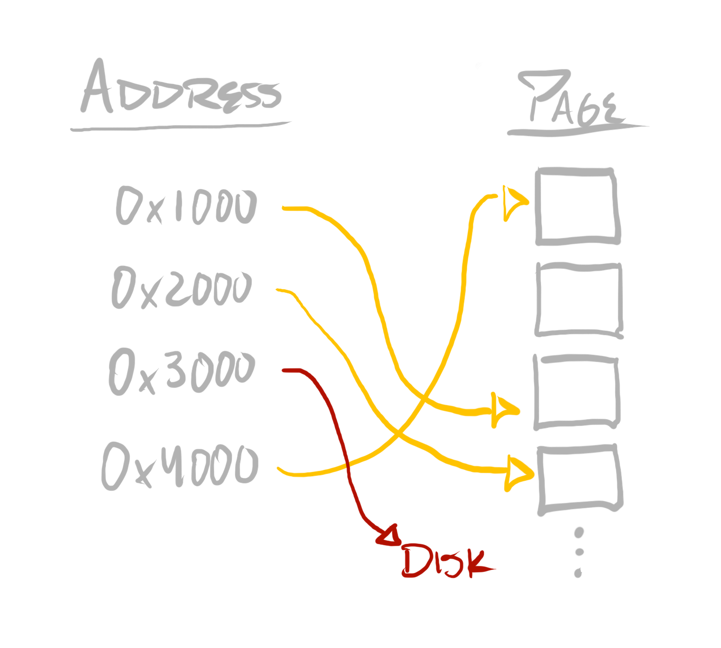
Virtual address spaces are implemented with a mapping data structure known as a page table. Page tables can be used to translate a virtual address to a physical address. They can then be used directly by the CPU in order to do address translation. For instance, if a CPU core were to execute a mov (move) instruction, to load 8 bytes from address 0x1000 into a register, then before issuing a read from physical memory, the CPU would first treat 0x1000 as a virtual address, and translate it into a physical address, which might be completely different—like 0x111000.
“Page tables” are called as such, because they map from virtual to physical addresses at page-size granularity. A system’s page-size varies—on an x64 Windows PC, it’ll be 4 kilobytes. On an iPhone, it’ll be 16 kilobytes. Operating systems also expose larger page sizes under some circumstances.
This means the relationship between physical memory and an address—as used by a program, as a virtual address—looks more like this:
If a virtual address cannot be mapped to a physical address, then a “page fault” exception is issued by the CPU, and execution is interrupted. If this is done by a program’s code, then execution will be transferred to the operating system’s code, which can take measures to address the cause of the exception and resume, or do whatever else it deems appropriate.
This provides a great deal of flexibility to operating systems. An operating system can move memory allocated by one program to disk—what’s known as “paging out”, or “swapping out”—if it expects that memory to not be accessed in the near future. It can then use that physical memory for more frequently accessed addresses, in any of the active virtual address spaces. If a page fault occurs when code attempts to access memory which has been paged out, then the operating system can simply page that memory back in, and resume execution. Thus, even though hundreds—if not thousands—of programs can be executing at once, the operating system can make much more efficient use of physical memory, given its analysis of which addresses in which spaces are needed, and when. This is critical in building operating systems which can support the execution of many programs, where all programs are contending for the same physical hardware.
It also provides a great deal of flexibility to programs, as it can be used to implement virtual address spaces which are much larger than physical memory. Nowadays, nearly every consumer CPU—from phones, to game consoles, to PCs, to laptops—is a 64-bit processor. For PCs and laptops running on 64-bit CPUs, the CPU and operating system normally provide a 48-bit address space. On some server systems, it is larger, and on some mobile and console platforms, it is smaller.
Taking a 48-bit address space as an example—48 bits allow the representation of 248 different values (each bit multiplies the number of possible values by 2). Since each value refers to a different potential byte, that is enough address space to refer to 256 terabytes.
To understand this further, let’s dissect the “page table” data structure a bit more.
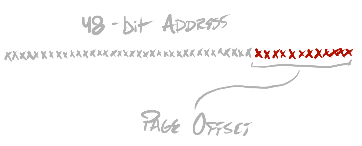
First, let’s assume a 48-bit address space, and a 4 kilobyte page size (the usual configuration on x64 Windows systems). As I said, page tables map from virtual to physical addresses at page-size granularity. Because of our 4 kilobyte page size, we can infer that the bottom 12 bits of any address are identical for both a virtual address and a physical address (212 = 4096 = 4 kilobytes).
This leaves 36 remaining bits, of each address, to map from virtual to physical addresses. These bits are used to index into several hierarchical levels, within the page table—it is actually a hierarchical data structure, despite its name, which sounds like it implies a flat table. To understand why, imagine, first, a naïve page table implementation, which simply stores a 64-bit physical address, for each value in this 36-bit space. This, unsurprisingly, would require an unrealistically large amount of storage. Instead, we can notice that the page table need only map virtual addresses which have actually been allocated. At the outset, none are allocated. When a virtual address space allocation is made, a hierarchical data structure allows the page table implementation to only allocate nodes in the hierarchy which are actually touched, by that one allocation.
Each node in the hierarchy can simply be a table of 64-bit addresses which point to children nodes (or, at the final level, it can store each page’s physical address). If each node is a 512-element table, and each element is a 64-bit address (8 bytes), then each node requires 4096 bytes, which is our page-size!
Because 29 = 512, we can slice our 36-bits into 4 table indices—each 9 bits—and use that to traverse the page table. The first 9 bits indexes into the first level, the next into the second, the next into the third, the next into the fourth—the fourth provides the base address of the containing page of our address, and then the bottom 12 bits can be used as an offset from that base.
For each virtual address space, the operating system manages this page table structure. Before the operating system prepares the CPU to execute code for one program, it can supply this table, such that the CPU can appropriately issue memory reads and writes to physical addresses for the appropriate virtual address space. The end result is that each program can, in effect, live in its own universe of virtual addresses, as if it had access to the entire system’s memory space, and if that memory space far exceeded the limitations of a system’s random access memory (RAM) capacity.
A bundle of state which is used to initialize the CPU to cohesively execute a sequence of instructions. Threads of execution are scheduled by the platform, such that many threads can execute on a small, fixed number of cores.
Beyond a page table, a CPU core requires other information to coherently execute code. For instance, it requires the “instruction pointer” (or “program counter”)—this is a register, which stores the virtual address of the next instruction which should execute, in a given instruction stream. After each instruction is executed, the value in this register is updated to reflect the base address of the next subsequent instruction. On x64, this is known as the rip register.
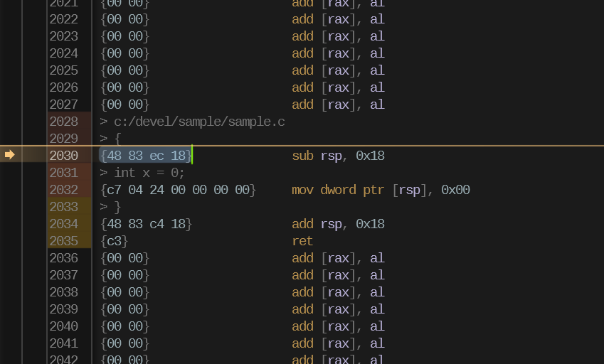
When using a debugger, you’ll often see golden arrows, pointing to lines of source code or disassembly. This directly visualizes the location of the instruction pointer.
There are several other registers, used for a variety of purposes, including general purpose slots for computations. The state of all such registers is called a “register state”, or “register file”. One register state is paired exclusively with one instruction stream, from one program—a register state should only change if a single instruction stream performs work which causes it.
But a CPU has only a fixed number of cores, be it 1, 2, 4, 8, 12, 16, 32, and so on—yet operating systems support a much larger number of programs executing simultaneously. Or, at least, it seems like they execute simultaneously.
The operating system implements this illusion—of hundreds if not thousands (if not more—unfortunately…) programs running simultaneously on a small, fixed number of cores—by scheduling work from these programs. One CPU core will perform work for one program, for some period of time—it will be interrupted, and the operating system can make the decision to schedule work from another program, for example.
A thread of execution is the name given to the execution state for one instruction stream. Each contains one register state, which includes the instruction pointer, and thus a stream of instructions—among whatever other state each operating system deems appropriate.
In other words, operating systems do not just schedule programs—they schedule threads. When an operating system schedules a thread, it incurs a “context switch”—this is the process of storing the CPU core state for whatever thread was executing to memory, and initializing that core to execute work for the thread which will execute.
A sequence of bytes encoding data in a platform-defined format, to encode executable machine instructions, as well as relevant headers and metadata. An independent code package’s non-live representation—a blueprint for execution.
On Windows, you’ll find executable images stored on the filesystem with a .exe, or a .dll extension. These files are stored in the Portable Executable (PE) format. The difference between .exe and .dll is that the former is used to signify that an executable image is a viable initial module for a process, whereas the latter is used to signify that an executable image is only to be loaded dynamically as an additional module for a process.
On Linux systems, there is a similar structure—executable images are stored on the filesystem (the extension convention varies—sometimes there is no extension for the equivalent of Windows’ .exe, sometimes there is a .elf extension, and for the equivalent of Windows’ .dll, the extension is generally .so). These files are stored in the Executable and Linkable Format (ELF).
When I say “these files are stored in” a particular format, what I mean is that the associated operating system’s loader expects files in that format. In order to produce code which can be loaded on a platform out-of-the-box, one must package that code in the format which is expected by that platform.
It’s not in this series’ scope to comprehensively dissect either the PE or the ELF formats. But to justify the definition and concepts I’ve provided, let’s investigate the PE format using a simple example.
First, consider the following code:
// sample.c

void WinMainCRTStartup(void)
{
  int x = 0;
}
This can be built with the following command, using the Visual Studio Build Tools:
cl /nologo /Zi sample.c /link /NODEFAULTLIB /INCREMENTAL:NO /SUBSYSTEM:WINDOWSThis command will produce an executable image, containing machine code. This machine code could be disassembled (for instance, using a debugger)—that would show something like this:
sub rsp, 0x18              ; - push 24 bytes onto the stack, for locals
mov dword ptr [rsp], 0x00  ; - set the 4 bytes we are using of the stack
                           ;     for `x` to 0
add rsp, 0x18              ; - pop the 24 bytes we pushed off the stack
ret                        ; - return to the caller of our main function
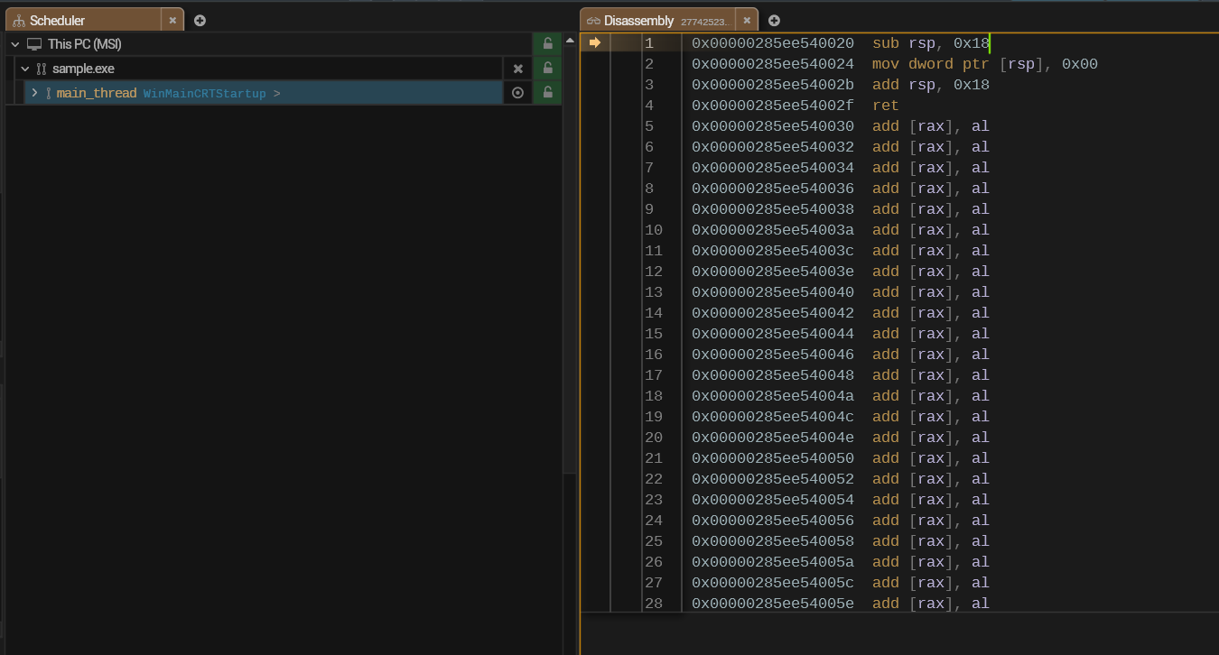
Even if we know nothing else about the PE format, we do know that these instructions need to be encoded somewhere in the file. We can identify how these are encoded using a disassembler tool as well, which should have an ability to visualize the machine code bytes which were parsed to form each instruction:
The above image shows the disassembled instructions in the RAD Debugger, as well as the bytes from which they were parsed. If you took a look at the disassembly yourself, and were confused by the add [rax], al instruction everywhere surrounding the actual code, the code bytes also clear that mystery up—that is simply the instruction one obtains when parsing two sequential zero bytes.
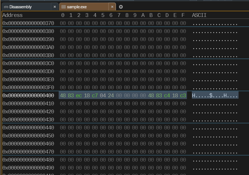
Given the above, we know that the generated machine code is encoded with 16 bytes. Each byte can be represented with two hexadecimal digits:
48 83 ec 18 c7 04 24 00 00 00 00 48 83 c4 18 c3If we look at the generated EXE with a memory viewer, we can, indeed, find this sequence of bytes.
We know that this sequence of bytes is the primary “payload”—the actual program code. Everything else in the file is used to either instruct the loader how to correctly prepare a process for this code to execute, or to associate various metadata with the code.
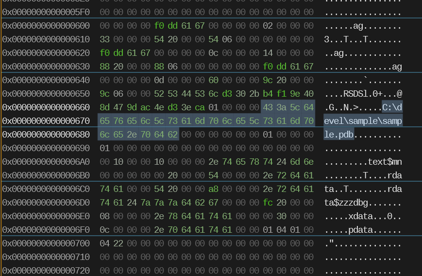
For example, if you scan around the file, you’ll find the full path to the debug information file (PDB) for the executable image.
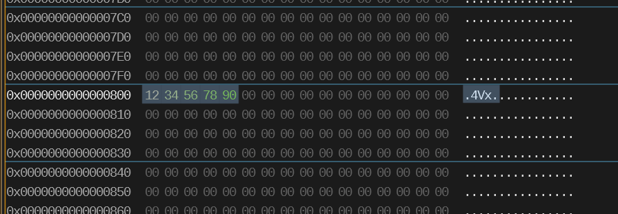
The executable image also must store data to which code refers. We can see this by inserting a recognizable pattern into a global variable:
// sample.c

static char important_data[] = {0x12, 0x34, 0x56, 0x78, 0x90};

void WinMainCRTStartup(void)
{
  int x = important_data[0];
}
We can also easily find the corresponding data in the PE file:
If you investigate formats like PE or ELF more closely, what you’ll find is that various categories of data—code, initialized global variables—are separated into sections. Each section has a name, which is also encoded in the file.
In PE, .text, for example, encodes all of the machine code (rather than, well, text…). .data stores data for initialized global variables. .rdata stores the same, but is separated to be allocated in read-only pages, such that code cannot modify that data.
.pdata and .xdata encode information about how, given a procedure, one may unwind a thread, to—for example—produce a call stack, which is simply recreating the information of which functions called which other functions in order to get a thread of execution to its current point in a procedure. But we’ll dig into that topic in a later post.
.edata and .idata encode information about exports and imports, respectively, which associate strings (“symbol names”) with locations in the file. An export is used by DLLs, for example, to export functions which can be dynamically loaded by name, by code in an executable or other DLL, and called. An import is used by either executables or DLLs to specify functions from other modules with which it must dynamically “link”.
When implementing a debugger, the precise details of formats like PE and ELF become relevant—but this should be a sufficient introduction for those unfamiliar with the basics.
A loader — The part of an operating system responsible for parsing executable images—blueprints for execution—and instantiating them, so that the code encoded in the images may be actually executed.
A module — The loaded equivalent of an executable image. One process can load several modules, although a process is always initialized by the loading of one specific module (the initial executable image). Modules can be both dynamically loaded and unloaded.
More than a debugger, a loader must be highly aware of executable image format details, because it has the task of parsing those images and making preparations, such that the code contained in the executable image can be executed.
A loader executes when a program is initially launched, or when actively-executing code requests to dynamically load another image—for instance, via LoadLibrary (Windows) or dlopen (Linux).
To understand this, let’s build a toy executable image format, and write our own loader, which parses our format, rather than PE or ELF.
Consider the following code, from earlier:
// sample.c

void WinMainCRTStartup(void)
{
  int x = 0;
}
And its disassembly:
> c:/devel/sample/sample.c
> {
{48 83 ec 18}              sub rsp, 0x18
> int x = 0;
{c7 04 24 00 00 00 00}     mov dword ptr [rsp], 0x00
> }
{48 83 c4 18}              add rsp, 0x18
{c3}                       ret
Our toy format can have a simple header, at the beginning of the image, containing the following values, in order:
-
An 8-byte signature, denoting that the file is in our format—must always be
54 4f 59 45 58 45 00 00—encoding the ASCII textTOYEXE, followed by two zero bytes. -
An 8-byte offset into the file, encoding where in the file all readable-and-writable global data is stored—the “data section”
-
An 8-byte offset into the file, encoding where in the file all read-only global data is stored—the “read-only data section”
-
An 8-byte offset into the file, encoding where in the file all executable data is stored— the “code section”
Each section size is determined by taking the next subsequent section offset (or the file size, in the case of the final section), and subtracting from it the section offset. If sections contain no data in any case, they will simply have the same offset as the next section.
Given this simple format, our full executable file for the simple example program can be encoded with the following bytes:
{54 4f 59 45 58 45 00 00} (magic)
{20 00 00 00 00 00 00 00} (read/write data offset)
{20 00 00 00 00 00 00 00} (read-only data offset)
{20 00 00 00 00 00 00 00} (executable data offset)
{48 83 ec 18 c7 04 24 00 00 00 00 48 83 c4 18 c3} (executable data)
In this case, our data sections are completely empty, because no global data is used by the code. Every section offset begins at offset 0x20 (or 32 bytes) into the file—or, directly after the header. The executable data section, being the final section, occupies the remainder of the file.
Our “loader” can define the format’s header with the following structure:
typedef struct ToyExe_Header ToyExe_Header;
struct ToyExe_Header
{
  U64 magic;       // must be {54 4f 59 45 58 45 00 00}
  U64 rw_data_off; // read/write
  U64 r_data_off;  // read
  U64 x_data_off;  // executable
};
It can begin by reading the file, and extracting the header:
// open file, map it into the process address space
HANDLE file = CreateFileA(arguments, GENERIC_READ, 0, 0, OPEN_EXISTING, 0, 0);
U64 file_size = 0;
if(file != INVALID_HANDLE_VALUE)
{
  DWORD file_size_hi = 0;
  DWORD file_size_lo = GetFileSize(file, &file_size_hi);
  file_size = (((U64)file_size_hi) << 32) | (U64)file_size_lo;
}
HANDLE file_map = CreateFileMappingA(file, 0, PAGE_EXECUTE_READ, 0, 0, 0);
void *file_base = MapViewOfFile(file_map, FILE_MAP_ALL_ACCESS, 0, 0, 0);

// extract the header
ToyExe_Header header_stub = {0};
ToyExe_Header *header = &header_stub;
if(file_base && file_size >= sizeof(*header))
{
  header = (ToyExe_Header *)file_base;
}
It can then allocate memory, big enough for the image’s data, and copy the file’s contents into that address range.
// allocate memory for all executable data - ensure it is all
// writeable, executable, and readable
void *exe_data = VirtualAlloc(0, file_size, MEM_RESERVE|MEM_COMMIT,
                              PAGE_EXECUTE_READWRITE);

// copy file's data into memory
CopyMemory(exe_data, file_base, file_size);
Given the header’s information encoding where in the executable data the code is stored, we can now call into that code directly:
// call the code
void *x_data = (U8 *)exe_data + header->x_data_off;
((void (*)())x_data)();
And it actually works! But there is, as you might expect, more minutiae to this in practice.
In this example, I’ve allocated all of the executable’s data with identical memory protections—all bytes in the executable’s data are legal to read, write, and execute. The point of having different sections at all is to organize data by how it will be accessed and used, so that—for instance—our “read-only data section” can actually be read-only (such that, if any code were to attempt writing to it, it would fail).
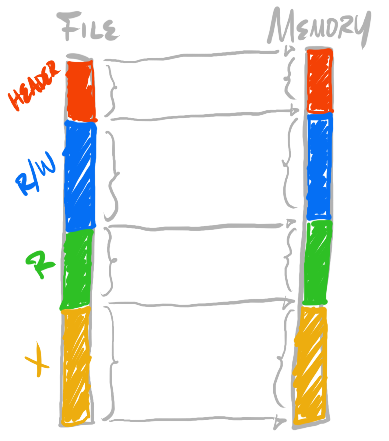
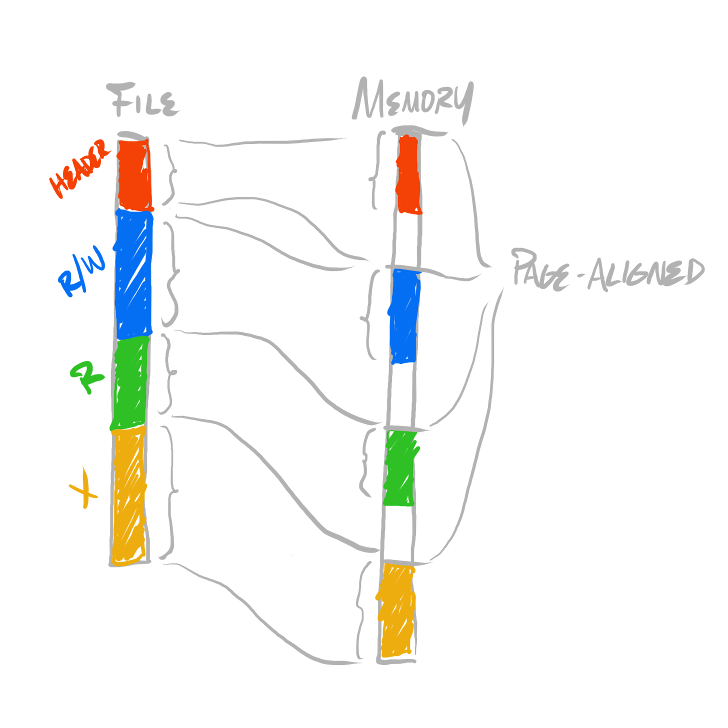
Because memory protections are assigned at page granularity, each individual section, after it’s loaded by our toy loader, must be at least one page size (so that we can assign appropriate protections to each section), and it must be aligned to page boundaries. But, were we actually designing a format, to require all sections be at least one page size (which is normally 4 kilobytes, if not larger), at least in the executable image itself (as it’s stored in the filesystem), can be fairly wasteful for smaller executables.
Instead of our loaded image being a flat copy from the image file:
We can adjust it to being an expansion for each section to page granularity, and a copy:
To do this, we can introduce a distinction between unloaded sections (that which stored in an executable image), and loaded sections (that which are loaded in memory, when a process executes). So far, our toy format has one notion of “offset”. We can break that down into two notions of offset, into two separate spaces—”unloaded space” and “loaded space”. These are generally called “file space” and “virtual space” (where “virtual” refers to a process’ “virtual address space”). Thus, instead of one type of offset, we can have file offsets, or virtual offsets. In code, instead of using off as our naming convention, we can explicitly encode which space we’re working within, by prefixing a name with either f or v. For example, “offsets” can now be referred to as either foff for file offsets, or voff for virtual offsets.
This distinction of unloaded and loaded images is the reason for the separation between the terms image and module. We call the image the “cold” equivalent of the data, and we call the module the “hot”—the loaded—equivalent of the data.
We can rewrite our header structure as follows, to encode both the locations of section data within the image, and to encode where the section data should be arranged within memory before execution:
typedef struct ToyExe_Header ToyExe_Header;
struct ToyExe_Header
{
  U64 magic;   // must be {54 4f 59 45 58 45 00 00}
  U64 padding; // (round up to 64 bytes)
  U64 rw_foff; // read/write (file)
  U64 r_foff;  // read (file)
  U64 x_foff;  // executable (file)
  U64 rw_voff; // read/write (virtual)
  U64 r_voff;  // read (virtual)
  U64 x_voff;  // executable (virtual)
};
Our test program can then be adjusted to the following bytes, assuming 4 kilobyte pages:
{54 4f 59 45 58 45 00 00} (magic)
{00 00 00 00 00 00 00 00} (padding)
{20 00 00 00 00 00 00 00} (read/write data file offset)
{20 00 00 00 00 00 00 00} (read-only data file offset)
{20 00 00 00 00 00 00 00} (executable data file offset)
{00 10 00 00 00 00 00 00} (read/write data virtual offset)
{00 10 00 00 00 00 00 00} (read-only data virtual offset)
{00 10 00 00 00 00 00 00} (executable data virtual offset)
{48 83 ec 18 c7 04 24 00 00 00 00 48 83 c4 18 c3} (executable data)
And our loader can be adjusted to perform the “expansionary copy”:
// unpack f/v dimensions of each section (and header)
U64 fdata_hdr_size = sizeof(*header);
U64 fdata_rw_size  = header->r_foff - header->rw_foff;
U64 fdata_r_size   = header->x_foff - header->r_foff;
U64 fdata_x_size   = file_size - header->x_foff;
U64 vdata_hdr_size = fdata_hdr_size;
U64 vdata_rw_size  = header->r_voff - header->rw_voff;
U64 vdata_r_size   = header->x_voff - header->r_voff;
U64 vdata_x_size   = fdata_x_size;

// round up virtual sizes to 4K boundaries
vdata_hdr_size+= 4095;
vdata_rw_size += 4095;
vdata_r_size  += 4095;
vdata_x_size  += 4095;
vdata_hdr_size-= vdata_hdr_size%4096;
vdata_rw_size -= vdata_rw_size%4096;
vdata_r_size  -= vdata_r_size%4096;
vdata_x_size  -= vdata_x_size%4096;

// calculate total needed virtual size, allocate
U64 vdata_size = (vdata_hdr_size + vdata_rw_size + vdata_r_size + vdata_x_size);
U8 *vdata = (U8 *)VirtualAlloc(0, vdata_size, MEM_RESERVE|MEM_COMMIT,
                               PAGE_READWRITE);

// unpack parts of virtual data
U8 *vdata_hdr     = vdata + 0;
U8 *vdata_rw      = vdata + header->rw_voff;
U8 *vdata_r       = vdata + header->r_voff;
U8 *vdata_x       = vdata + header->x_voff;

// unpack parts of file data
U8 *fdata         = (U8 *)file_base;
U8 *fdata_hdr     = fdata + 0;
U8 *fdata_rw      = fdata + header->rw_foff;
U8 *fdata_r       = fdata + header->r_foff;
U8 *fdata_x       = fdata + header->x_foff;

// copy & protect
CopyMemory(vdata_hdr, fdata_hdr, fdata_hdr_size);
CopyMemory(vdata_rw, fdata_rw, fdata_rw_size);
CopyMemory(vdata_r, fdata_r, fdata_r_size);
CopyMemory(vdata_x, fdata_x, fdata_x_size);
DWORD old_protect = 0;
VirtualProtect(vdata_hdr, vdata_hdr_size, PAGE_READONLY, &old_protect);
VirtualProtect(vdata_rw, vdata_rw_size, PAGE_READWRITE, &old_protect);
VirtualProtect(vdata_r, vdata_r_size, PAGE_READONLY, &old_protect);
VirtualProtect(vdata_x, vdata_x_size, PAGE_EXECUTE, &old_protect);
And—since it’s easy to notice that this is getting rather repetitive for each section—we can table-drive this “expansionary copy”. Doing so will eliminate most of the per-section duplication:
// gather all information for all boundaries between all sections (& header)
struct
{
  U64 foff;
  U64 voff;
  DWORD protect_flags;
}
boundaries[] =
{
  {0,               0,               PAGE_READONLY},
  {header->rw_foff, header->rw_voff, PAGE_READWRITE},
  {header->r_foff,  header->r_voff,  PAGE_READONLY},
  {header->x_foff,  header->x_voff,  PAGE_EXECUTE},
  {file_size,       0,               PAGE_READONLY},
};
U64 region_count = (sizeof(boundaries)/sizeof(boundaries[0]) - 1);

// calculate vsize for all regions
U64 vdata_size = 0;
for(U64 idx = 0; idx < region_count; idx += 1)
{
  U64 vsize = (boundaries[idx+1].foff - boundaries[idx].foff);
  vsize += 4095;
  vsize -= vsize%4096;
  vdata_size += vsize;
}
boundaries[region_count].voff = vdata_size;

// allocate; iterate regions, do copy & protect
U8 *vdata = (U8 *)VirtualAlloc(0, vdata_size, MEM_RESERVE|MEM_COMMIT,
                               PAGE_READWRITE);
U8 *fdata = (U8 *)file_data;
DWORD old_protect = 0;
for(U64 idx = 0; idx < region_count; idx += 1)
{
  CopyMemory(vdata + boundaries[idx].voff,
             fdata + boundaries[idx].foff,
             (boundaries[idx+1].foff - boundaries[idx].foff));
  VirtualProtect(vdata + boundaries[idx].voff,
                 (boundaries[idx+1].voff - boundaries[idx].voff),
                 boundaries[idx].protect_flags, &old_protect);
}
It’s not much shorter, but all work for all expanded and copied sections has been deduplicated. In order to adjust this for a larger number of different sections, only the boundary table must change.
Now that we have a basic structure for loading our image format, let’s consider how a loader is used. As I’ve stated, an executable image is loaded whenever a program is launched, or when an executing program requests to dynamically load another image (for instance, through LoadLibrary or dlopen).
We’ve already explored the first case—program launching—as that will consist of simply beginning execution of the program. With our toy loader, we can just immediately execute the code after we’ve loaded it:
// call the code
void *vdata_x = (U8 *)vdata + header->x_voff;
((void (*)())vdata_x)();
This makes the assumption that the first instruction stored is our entry point. If we ever wanted that to not be the case—as “real” executable image formats do—then we can simply store a virtual offset for the desired entry point within the image’s header.
But in the case of dynamic loading, our loader’s job is not to merely begin executing at a single point in some code. Our load instead must load the image, and prepare for dynamic lookups of potentially many named entry points. On Windows, the usage code for this looks something like:
HMODULE foo_library = LoadLibraryA("foo.dll");
void (*foo_function)(void) = GetProcAddress(foo_library, "foo_function");
foo_function();
To facilitate this path, our executable image format must associate a number of names—like foo_function—with specific virtual offsets in the executable data section. This concept is known as an executable image’s exports, and it can be straightforwardly encoded as a set of pairs of names and virtual offsets.
There’s a symmetric concept known as imports, which function as a fast path for the manual lookup of functions from a loaded executable image like the above code. On Windows, the usage code for that looks something like:
__declspec(dllimport) void foo_function(void);
#pragma comment(lib, "foo.lib")
foo_function();
Both explicitly loaded (via GetProcAddress on Windows, or dlsym on Linux), and implicitly loaded (via __declspec(dllimport) on Windows, which is more automatic on Linux toolchains) functions are called through a double indirection. To perform an actual function call, first the CPU must follow the address of the pointer in which the loaded address is stored, then it can use whatever the value of that pointer as the address of the function to call.
In the above example with explicit loading, the address of the loaded function is stored in the explicit foo_function function pointer variable. In the above example with implicit loading, the address of the loaded function is implicitly stored in hidden state, as an implementation detail.
When an executable image has imports, in order for the loading of that image to succeed, the associated imports must be dynamically linked. This will be done automatically, as opposed to the program code manually calling—for instance—LoadLibrary or GetProcAddress.
Machine code contained in an executable image can be hardcoded to refer to specific addresses. But as you’ll notice, in our toy loader, we don’t control which address at which our module for an image is placed in memory. We call VirtualAlloc to allocate memory for our module data, and whatever address it returns, we use that. Of course, we can request that VirtualAlloc place our allocation at a specific address, but that is not necessarily guaranteed to succeed.
This means that if we, for instance, had an image with instructions which referred to a global variable’s absolute address, they would only be valid given that the image is loaded at a particular address.
In principle, a loader could guarantee a fixed virtual address for a program’s initially loaded executable image. They don’t. But in any case, that cannot generally be true, because images can be loaded or unloaded dynamically, and they are not built to be aware of which other images are loaded simultaneously. Thus, they must be dynamically arranged—each image’s code should be able to operate correctly, irrespective of where its loaded module equivalent is placed in memory.
In many cases, especially nowadays, addresses are encoded as relative to some offset into code, in which case they’re always valid, irrespective of which runtime address at which the module is loaded. But, nevertheless, there still exist mechanisms for code to be hardwired to refer to specific addresses. In such cases, an executable image also contains relocations, which encode locations within the executable image which must be reencoded after the base address of the loaded image is determined at runtime.
It is the loader’s job to iterate these relocations, and patch in the appropriate addresses given the only-then-available knowledge of where the image’s loaded data is actually stored.
An instance of a live, running program. Instantiated by the platform’s loader using the initial executable image to determine how it’s initialized, and what code is initially loaded. The granularity at which operating systems assign virtual address spaces. The container of several modules, and threads of execution.
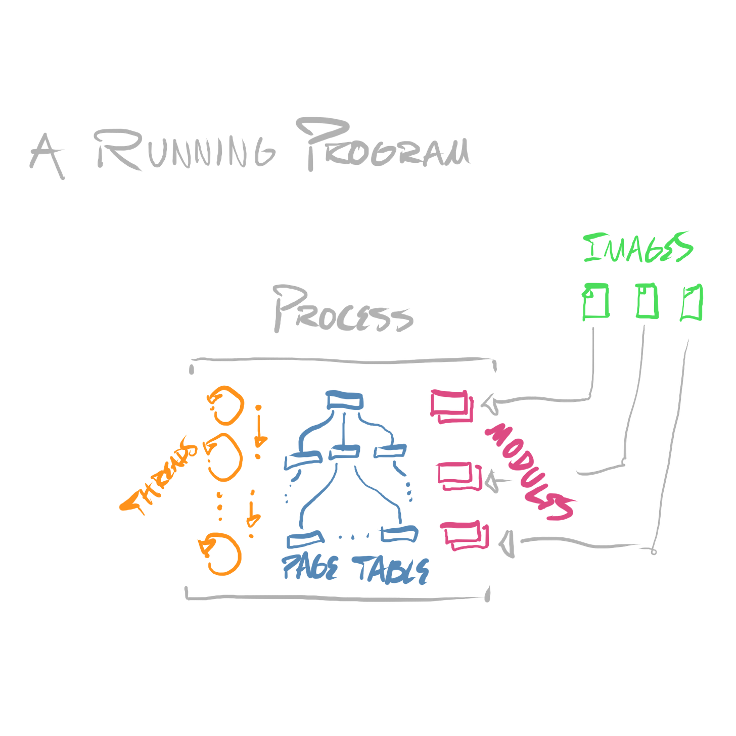
We’ve covered everything we need to sketch out a definition of a process—a running program.
Each process is the owner of some number of threads, and some number of modules. It is the owner of a single virtual address space.
Threads and virtual address spaces are, in a sense, orthogonal concepts—threads are used to virtualize CPU cores, virtual address spaces are used to virtualize physical storage—the process is the concept which binds them together.
When a program is launched, a process is created, an executable image is loaded to produce an initial module, and an initial thread is spawned.
An operating system’s scheduler then considers that process’ main thread as a viable candidate for scheduling. When it’s scheduled, the program executes.
When a debugger is used to analyze another program, it does so at process granularity. It is registered by the operating system as being attached to a process. When a debugger is attached to a process, the operating system enables additional codepaths, which report information about that process’ execution to the debugger’s process. If that information includes addresses, they’re reported as virtual addresses, within the address space of the process to which the debugger is attached.
But that’s enough for now! We’ll dig into exactly what kind of information an operating system reports to a debugger process, how it can do so, and how the debugger can interact with the debugged process, next time.
If you enjoyed this post, please consider subscribing. Thanks for reading.
-Ryan

