Home
The Knight TV system was a terminal system made by
Tom Knight
that was connected to the AI KA10.
It used a PDP-11/20 whose Unibus was directly connected
to the PDP-10 by the 10-11 interface that was
unique to AI. (At first we though it was an 11/10,
but that doesn’t seem to have been the case)
The PDP-11 had 12kw of memory and a number of
16kw bitmap frame buffers that could be mapped
into the address space of the Unibus.
The frame buffers generated a video signal that
was used as input for a video switch
configured by the PDP-11.
The output of that video switch was fed into
the TV sets which were used as terminals.
For input there was a keyboard multiplexer
to which the Knight keyboards were attached.
The file .; TV BIN can be loaded into the 11
from the 10 with the STUFF program,
then the 10 and 11 communicate via shared memory.
The Knight TV system was the preferred way to talk to ITS
for a while so there was not question it had to be resurrected!
Planning
Lars and I
talked about how this multi-level design should be implemented.
We had Rich’s
simh-based KA10 emulator to run ITS.
The first question was whether to use simh to emulate the PDP-11
or write a new emulator.
As I find simh code rather hard to read and because emulation is
fun we decided it would all be new code.
Also, since there is only one 11 but multiple displays/keyboards,
the 11 would best run as a server to which clients then connect.
This would also allow multiple people connected to the same
remote system to spy on each other’s consoles,
an important feature.
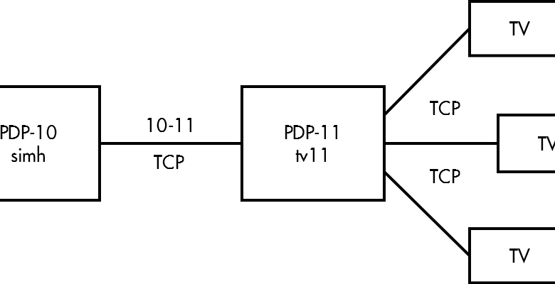
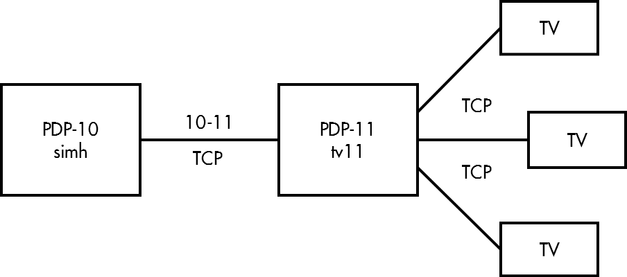
The idea was to have the 10 and 11 emulators run on the
same machine and have TV clients connect from remote.
Network connects are an easy way for processes to communicate
so we decided to use a simple protocol to implement
the 10-11 interface.
PDP-11 emulation
Writing emulators is fun and especially in the case of the PDP-11/10
it’s easy enough to be done in a couple of days.
Since at first we thought it was a PDP-11/10 that was running the
TV system, that’s what I wrote an emulator for.
It worked because the difference to an 11/20 isn’t that great.
I later modified the emulator to behave more like an 11/20
but the following describes how I wrote the first version.
The PDP-11/10 is in fact the same model as the 11/05 and
all relevant documentation can be found on
bitsavers.
It is a low-end model very similar to the original PDP-11/20:
microcoded (unlike the 11/20),
16 bit address space,
no extended instructions (multiply, divide, &c.).
A couple of peripherals are included in the 11/05 as part of the CPU:
a KW11 line clock look-alike, and a KL11-like TTY interface.
Since it has no extended instructions,
the MIT hackers equipped the TV 11 with the KE11 extended arithmetic module,
a device that sits in the Unibus IO page and is controlled
by writing values to a number of mapped registers.
I considered writing a rather low level emulator that
would actually execute the microcode but decided against it.
Instead I wrote some higher level code that was still
inspired by the schematics and microcode.
The emulator is written in C.
In the PDP-11 all IO devices and memory are connected to the Unibus
(this is not the case in all models, but in our case it is).
The CPU is the bus master that arbitrates access to the bus.
When a device needs access to the bus it will request bus access
with one of 4 priorities (4-7).
To model this I made a struct for the CPU, the Bus and
devices connected to the bus:
// KD11-B is the 11/10 processor
struct KD11B
{
        word r[16];   // register scratchpad
        word ba;      // bus address
        word ir;      // instruction register
        Bus *bus;     // our lovely Unibus
        byte psw;     // processor status word
        int traps;    // flags to keep track of traps
        int be;       // counter for bus errors, to catch double bus errors
        int state;    // halted, running or waiting

        // Keep track of bus requests for all channels
        struct {
                int (*bg)(void *dev);   // Bus grant callback
                void *dev;              // device that requests bus access
        } br[4];

        word sw;      // console switch register

        // omitted: internal devices
        // line clock
        // ...
        // TTY input
        // ...
        // TTY output
        // ...
};

// Unibus
struct Bus
{
        Busdev *devs;   // linked list of devices on the bus
        uint32 addr;    // addresses are 18 bit
        word data;      // data is 16 bit
};

// A device on the bus
struct Busdev
{
        Busdev *next;   // next in list
        void *dev;      // pointer to individual device's struct
        int (*dati)(Bus *bus, void *dev);   // read data from device
        int (*dato)(Bus *bus, void *dev);   // write data (word) to device
        int (*datob)(Bus *bus, void *dev);  // write data (byte) to device
        int (*svc)(Bus *bus, void *dev);    // service callback,
                                            // returns bus request priority if any
        int (*bg)(void *dev);               // bus grant callback,
                                            // returns interrupt vector
        void (*reset)(void *dev);           // reset device
};
The internal devices do not use the Bus, they’re handled by CPU code.
For a given address a device which recognizes the address
will respond.
If no device responds, the access times out and the CPU
receives a bus error.
With bus grants, the electrically nearest device will receive
the grant and pass it on to the next device if it didn’t request
bus access.
I modeled this mechanism with a linked list.
For all device specific behaviour there are virtual functions
that correspond to unibus transactions.
While the CPU is running (i.e. not halted) it will execute
instructions.
If it is waiting it will not execute instructions until an interrupt
occurs (this is indicated by a bit in the traps variable).
The main loop does the expected, in pseudocode:
while state != halted
    service-internal-devices()
    service-bus-devices()
    if(state == running || state == waiting && traps)
        state = running
        execute-next-instruction()
Instruction execution is much like you would expect
from an emulator, if you’re not familiar with the PDP-11
instruction set, a quick summary:
The PDP-11 has 8 general purpose registers
and 8 addressing modes,
that makes 6 bits to encode any register+mode combination.
Some instructions have two operands
(so 12 bits are needed to encode both),
some have only one operand (6 bits),
branch instructions have a signed 8 bit word offset,
the other instructions have no operands.
All double operand instructions
first read the source operand and store it in temporary register R10,
read the destination operand and store it in R11,
execute the operation (they’re all very simple ALU operations)
and store the result back at the destination address,
which was kept unchanged in the BA register.
Unary instructions work almost the same,
there just isn’t a source operand.
Branch operations add the branch offset depending
on which status bits are set.
K11-A – EAE
The K11-A module is the extended arithmetic extension,
it implements multiplication, division, logical and arithmetic shifts
and normalization.
The manual
is very well written and I recommend anyone interested in how
computers do math to read it.
The way it works is that you set its AC and MQ registers by writing
to their unibus addresses and then write a third value
to another address to kick of the calculation.
You then read back the result from AC and MQ from the same addresses.
Implementation was rather straight forward,
I simply transcribed the flow diagrams into C.
The TV hardware
The TV hardware consists of essentially three parts:
the bitmapped frame buffers, the video switch and the keyboard multiplexer.
Luckily the TV code is very well commented so figuring out how they all work
was not too hard even if a bit confusing.
The console frame buffers
The setup has a maximum of 16 frame buffers.
Each FB has a resolution of 576×454 pixels,
with 16 pixels per word that makes
037730 PDP-11 words, almost 16kw.
CREG (at 0164044) maps one of up to theoretically 256 FBs
to 060000 on the Unibus and sets the ALU operation that is
to be done on a write to the buffer memory.
For faster changes to the FB the hardware can perform 16
different ALU operations itself instead of having the PDP-11 do them.
The video switch
Each of these 16 buffers are now fed into the inputs
of the video switch
that sends the video signal of every frame buffer to any
number of TVs.
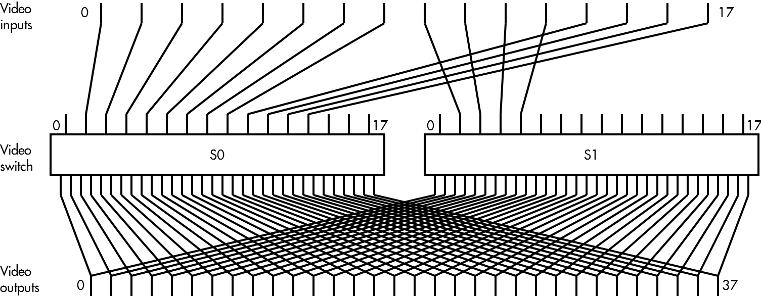
The video switch is made up of two sections (S0 and S1 below),
each having 16 inputs and 32 outputs.
The corresponding outputs of both sections are mixed together
to form the final signal for the TV.
Since in the normal case you don’t want to mix anything
with the consoles,
both sections have a null input on input 0,
which leaves 15 inputs per section for the consoles.
This shows how the 16 console frame buffers
are fed into the video switch
and how the output is mixed.
The VSW register (at 0764060) controls the switch.
For a section, input and output number
it sets the source of the ouput of that section
to the given input of the section.
Thus every console can be displayed on every TV
by setting the output of the section the buffer is connected
to to that buffer and the same output on the other
switch to 0.
The keyboard multiplexer
Up to 64 keyboards can be connected to the keyboard mux.
It is controlled by the registers KMS (keyboard status, at 764050)
and KMA (keyboard address, at 764052).
When the multiplexer receives a key press from one of the keyboards,
it will DMA it together with the keyboard number into a buffer in memory,
the address of which is given by KMA.
It will also interrupt the CPU so that it may read the new key
and handle it.
Emulating all of this
Implementing this in C is pretty straightforward.
It gets a bit complicated by the way how the video switch works.
Because every console buffer can be displayed
on every display and also be mixed with another signal,
it makes updating the TV client programs a bit more complex.
Source code
Finally, here you can find source code:
https://github.com/aap/pdp11
together some other PDP-11 emulation projects.
The ITS build script
automatically builds and starts it when ran with ./start tv11.
You can then connect to the 11 with tvcon.
The keyboard layout is modeled after the original layout,
but there are command line options to make it a bit more pleasant.
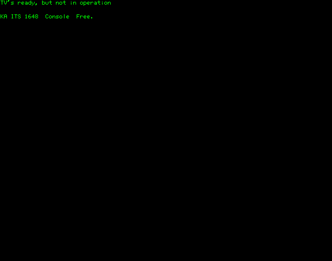
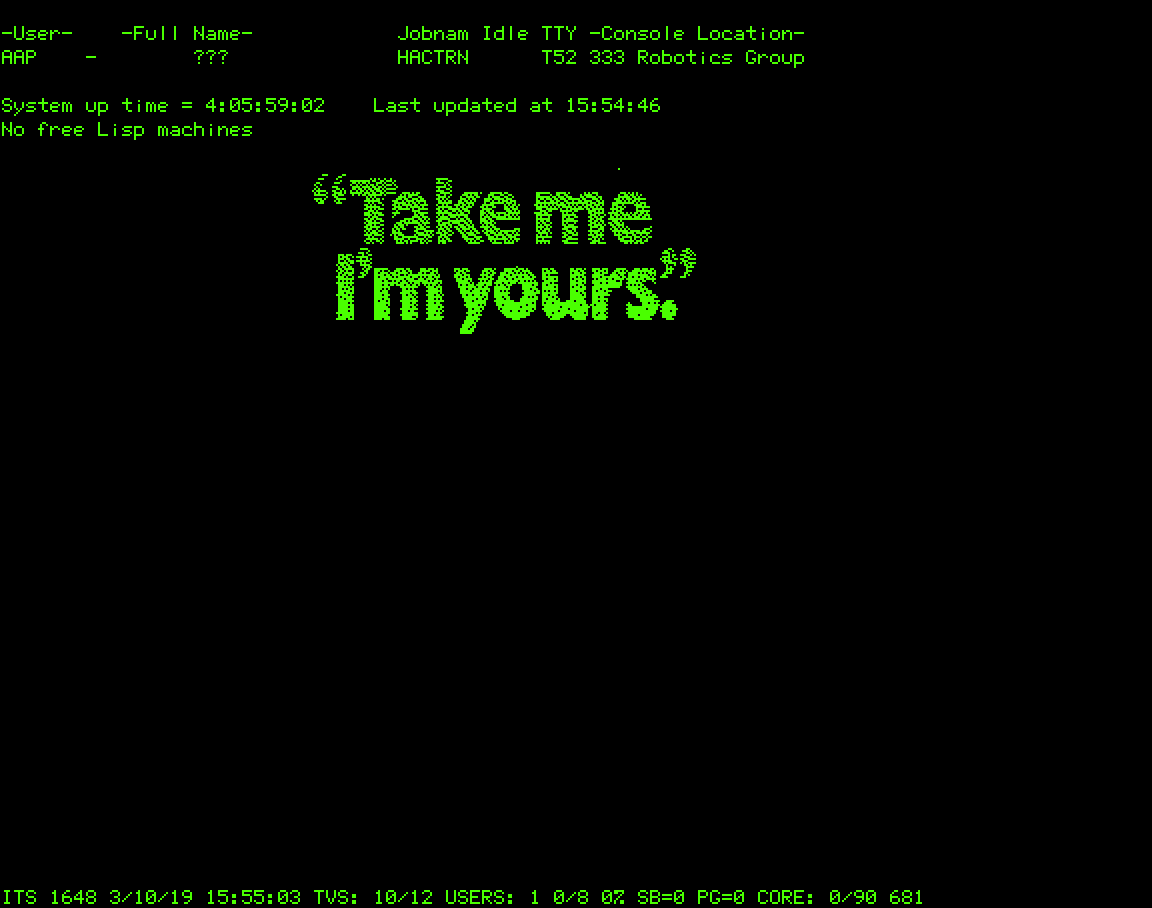
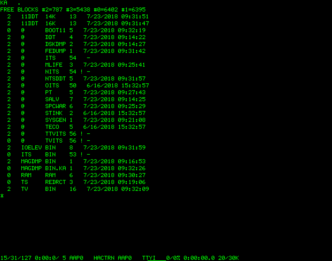
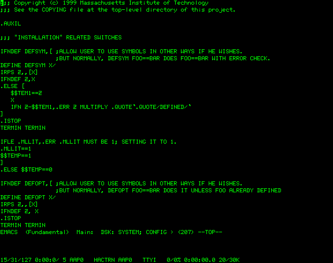
Screenshots